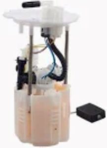
A fuel pump wiring diagram tells you the outputs, inputs, electrical circuits and connectors of your fuel pump circuit. It demonstrates that; the fuel pump is part of the electrical system for your vehicle, and shows you what wires connect on your battery,fuse box,fuel pump relay, ignition switch. Wire colors, sizes and voltage requirements are typically labelled in these diagrams. This means, for example, the wiring diagram must maintain good electrical connections to keep delivering power at 12 volts for a fuel pump and other parts of the system so that it works together.
When the fuel pump malfunctions, you use a wiring diagram to diagnose the problem. A degradation in fuel pump output as low as 10-20% can be induced by poorly performing wire or connection, resulting in delivery problems such as stalling or no-start. Technicians can use the wiring diagram to check for continuity in the wiring harness, find blown fuses, and create a visual of where in the circuit there may be faulty relays. If the pump is not getting its full 12 volts due to a wiring problem, for example, it alerts the technician to look further up the diagram (toward the battery) to find where that problem lies and apply the correct fix.
For high-performance applications that might exceed 255 liters per hour (LPH) in flow, you need a properly wired fuel pump that isn't going to load your car with increased voltage drops. Voltage needs to be kept up for the fuel pump, a 12 v one may work at 10 v but guarantee you would never keep working right and it is a solid reduction based on the voltage drop, for example -15% compared to triggered routine /engine idle scrolls). The wiring diagram is an important thing for good current flow and most efficient which helps to the fuel pump wiring system.

These wiring diagrams are crucial since fuel pump wiring is usually very complicated, especially if you are installing an aftermarket fuel pump. The turbo manufacturers and the OEMs believe that it does,, but numerous aftermarket systems need to be hacked into their factory wiring to be able to support higher power requirements or components like a dual fuel pump system. During the installation, an inflow of high pressure fuel may overheat motor and causes electrical shorts. Both may damage the fuel pump and vehicle electrical systems when wiring incorrect.
For example, in an infamous situation within the automotive sector, a recall of more than 100,000 vehicles may have been connected to fuel delivery issues and engine stalls due to improperly wired fuel pumps. Ultimately, this case helps to demonstrates the importance of precise adherence to wiring diagrams — both for safety and performance. It keeps a damaged fuel pump, which usually has an operational lifespan of between 100,000 and 1500,00 miles from causing more problems.
For an even more detailed look at fuel pump wiring and installation, go to this link Fuel Pump